Two years after the first project the G150 was drawn, (1996) I decided to continue to fly along that track but this time working on a brand new idea. A kind of concept radically review of the originate G150 that would take me up to the next level was my next target, designing a brand new aircraft, wider than the G150 with at least four seats. The G416B is indeed quite compact provided of a different type of propulsion technologically affordable at the time since the way I imagined electric motors wasn't conceivable yet in 1998 I take the Hybrid option as main platform to work on developing a machine more realistic at least in the late 90's. The G150's project was in fact partially solved right since I had no idea of what kind of electric motor I could find to instal in that aircraft and only some years later in 2003. I found the answer I was looking for in a japanese project adressed to automotive, an electric car provide of eight in-wheel induction motors electronically controlled with a sophisticate system driven by a special software that allowed the Eliika to reach 400 km/h on the track, and this sparkled a bright flash in my mind making me to reconsider the full electric option for aviation propultion, but this is another chapter.
The concept
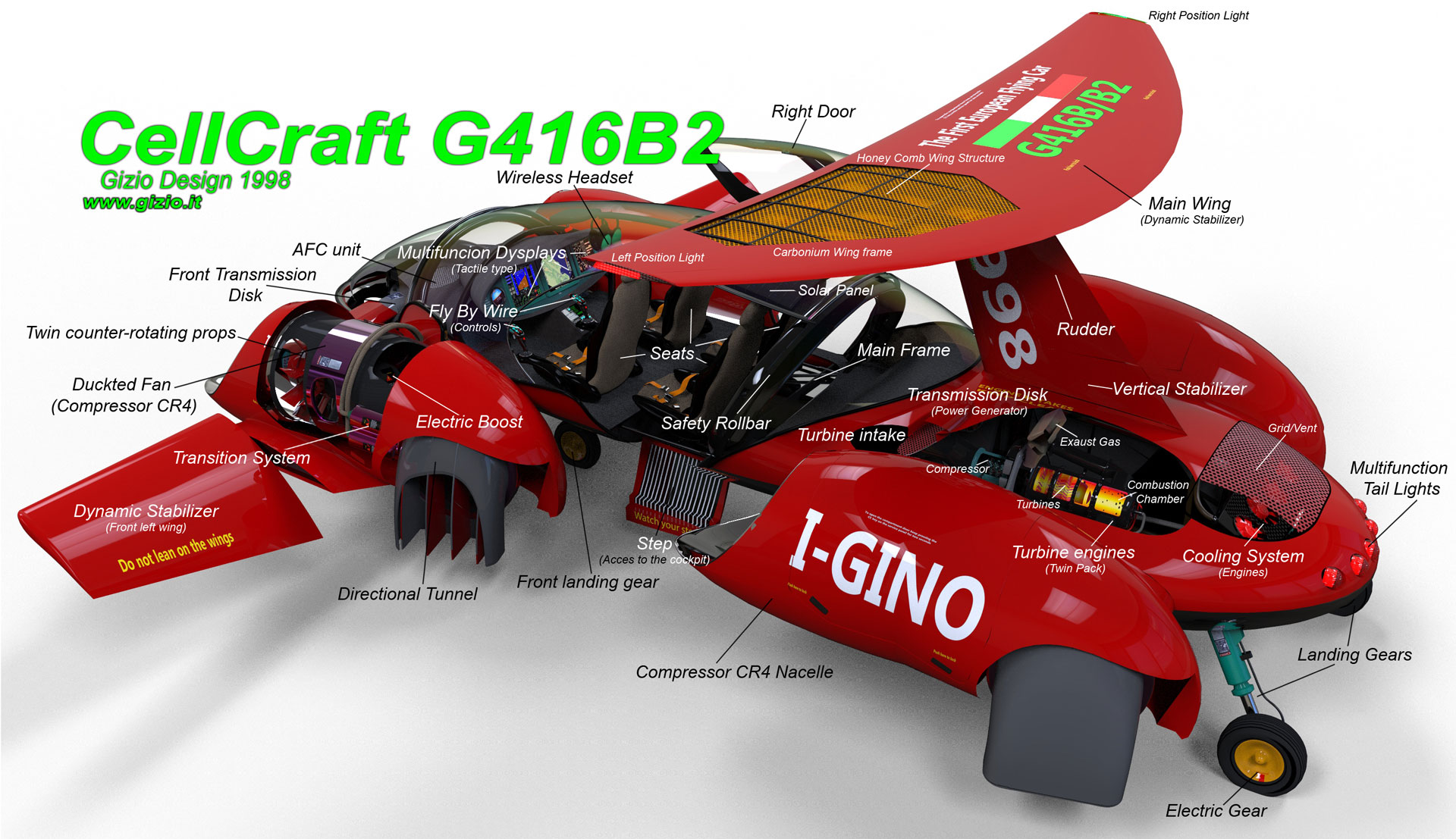
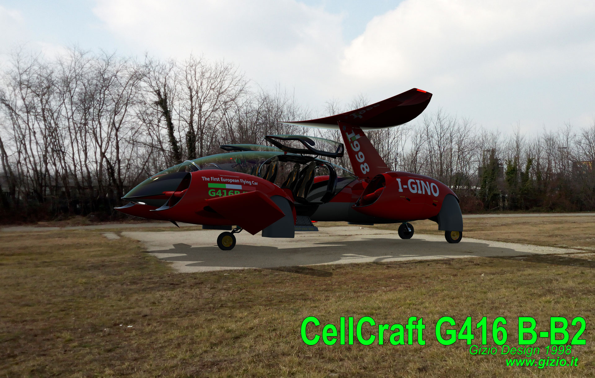
The aircraft’s body was built with an aluminum bottom fixed on a super light steel’s frame while other elements were made of plastics and carbonium. The main concept for this project was to make a larger aircraft compared to the preceding single seat project: the G150.
The
G416 was pretty much different if compared to a common
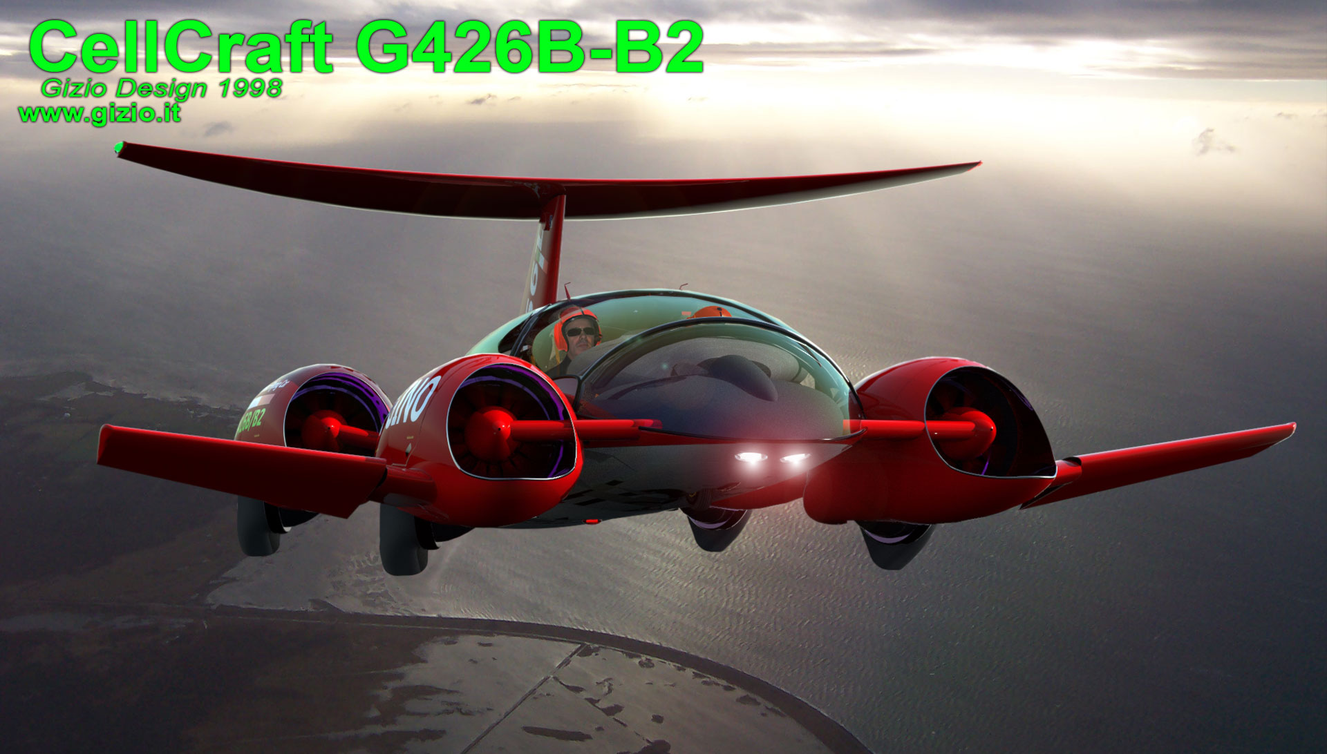
aircraft, it was provided of a big transparent dome, with a wide area
covering over 35 percent of the whole aircraft surface.
Another point as well important about this project, and those who followed
it later, was also taking the advantage of the aerodynamic shape of the
whole fuselage’s surface in order to increasing aerodynamic efficiency
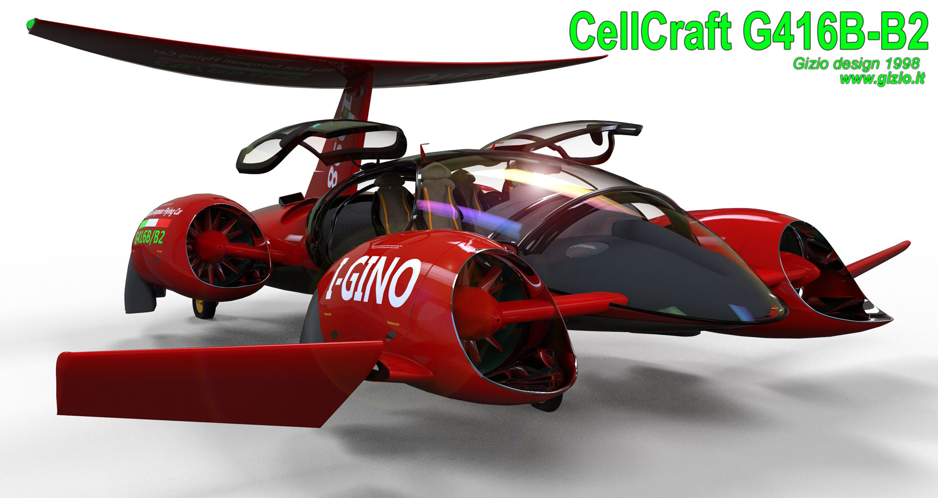
and lifting capability. The engine compartment was settled at the rear
of the main body of the aircraft, actually under the main wing attack,
pretty much in correspondence of the center of gravity, which in this
aircraft was pretty much aft shifted.
Transmission Disk provided the distribution of power between turbine’s
engine and rotors, the two disks were placed respectively one in rear
and the other one in the front area of the fuselage, each one of them
is provided of an electric generatori and they are both connected with
a longitudinal tubular shaft.
3D modeling software opened up a wide view to my design technique since I got the possibility, to design this and many other projects in every single detail; considering the real space, volume, and finally refining details of any single component. The digital tool allowed me to work with precision, but also making at the same time a multitude of virtual materials “creating” an extremely accurate and realistic model, which matched exactly to what I have in my mind.
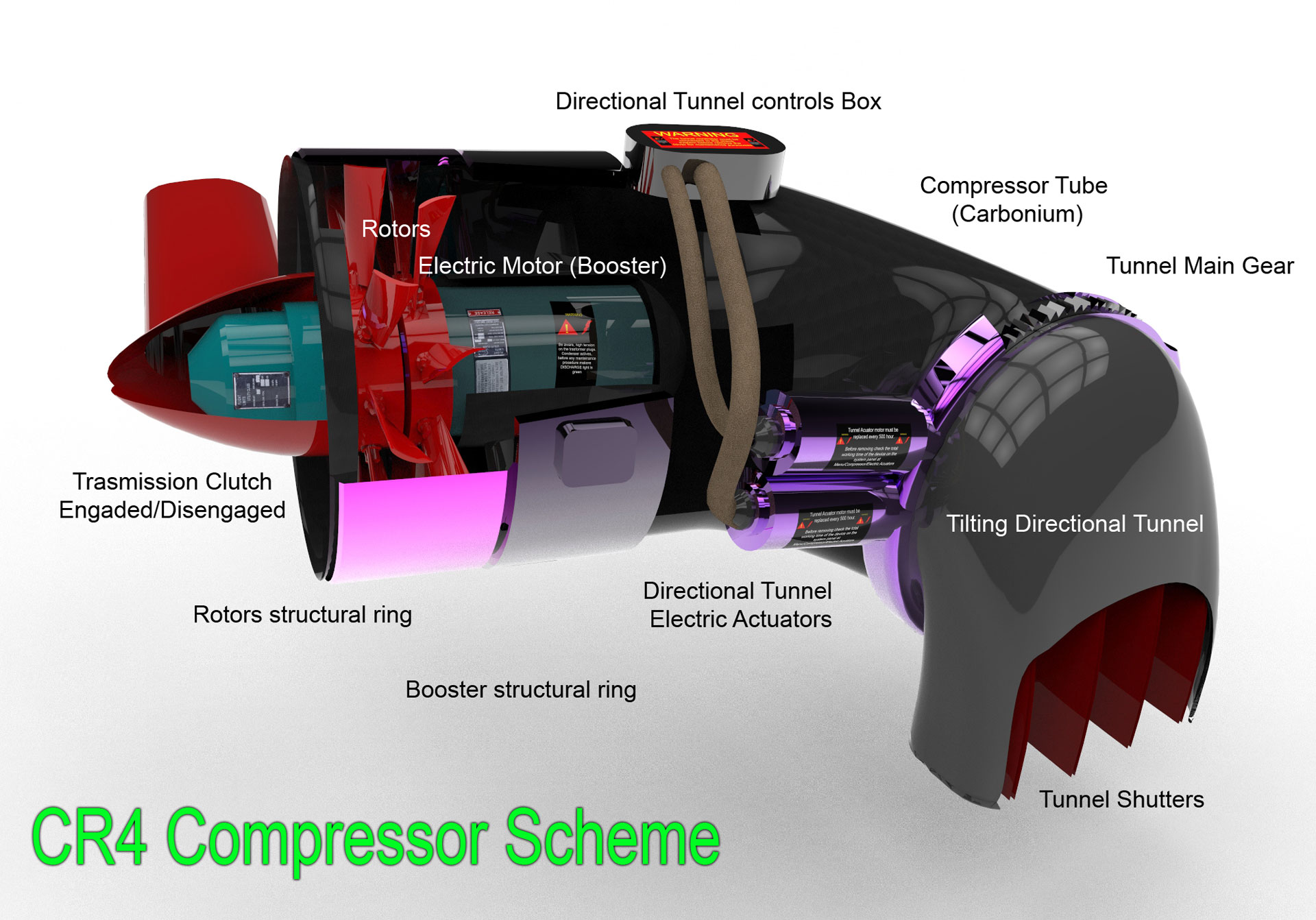
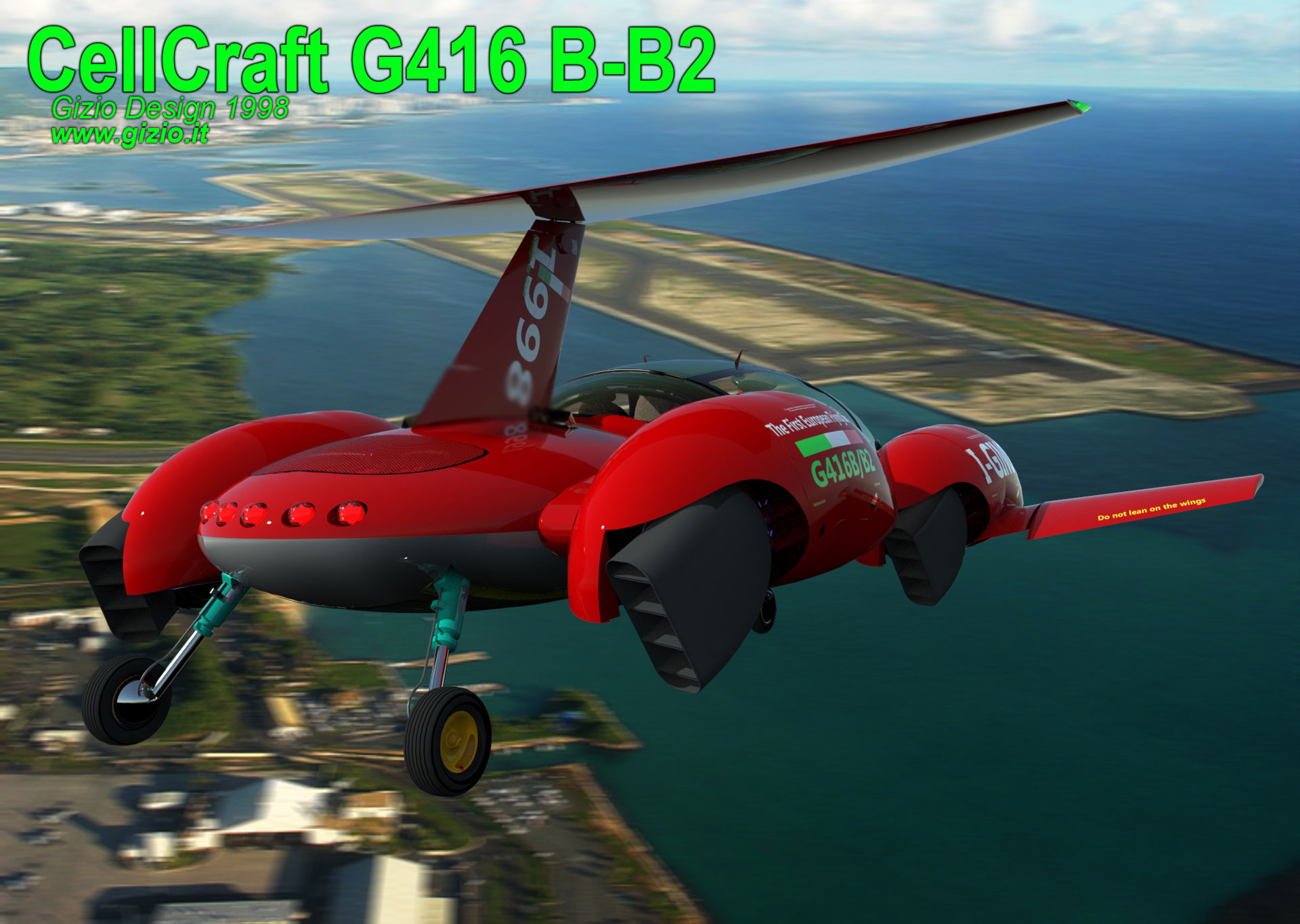
Compressors
or ducked rotors were all housed in four nacelles, arranged on each
side of the fuselage. The Ducted rotor or compressor's internal chamber
reminded that of a Venturi’s tube profile, inside of which were
housed two large counter-rotating fans connected to the disc transmission
system through tubular shafts, furthermore the rotor couple were provvided
of an internal electric motor. The electric boosters were operated only
in situations where the required power were necessary as the maximum
available at the moment, while in hover flight or during take off or
landing to support the weight of the aircraft in flight at the best.
The air circulating inside the compressor in the frist version of the
G416 was heated through
a sort of ring grid that mixed the exhaust gases coming from both turbines
recycling it mixing the hot gases with the air flow pumped inside the
chamber in all the compressor’s rotors hoping to increasing thrust,
thanks to hot gas expansion property but some calculations later demostrated
that this option was not optimal for such type of aircraft.
The main stream of compressed air followed a path before be deflected
through the tilting splitter, which deflected the compressed air flowing
in the desired direction. All the four splitters reminded in some ways
those installed on the Harrier having the same function
but quite larger on CellCraft G416.
Since the first project I’ve considered the adoption of special type of seats, particularly light, having a pneumatic chambers fixed on a sort of aluminum frame making each seat pretty light but also comfortable at the same time. The seats were conceived as an important element of the machine. It was a draft made some years earlier which contained inside a series of sensors and accelerometers connected to a small gyroscope which measured the variation of weight, varying by the gravity’s acceleration occuring during the different phases of the flight. The flight management system; the AFC (Automatic Flight Control) was and still is, the main electronic device adopted for a perfect control of the asset of the aircraft in flight. It correct any variations or attitude balancing the position of the aircraft in the space instantly. The flight controls of the aircraft were also integrated on both sides of the pilot’s seat rather than mounted on the main aircraft body, and then was the time when the Smart Chair has born and it is largely employed today in all CellCraft and Verticraft projects of mine.
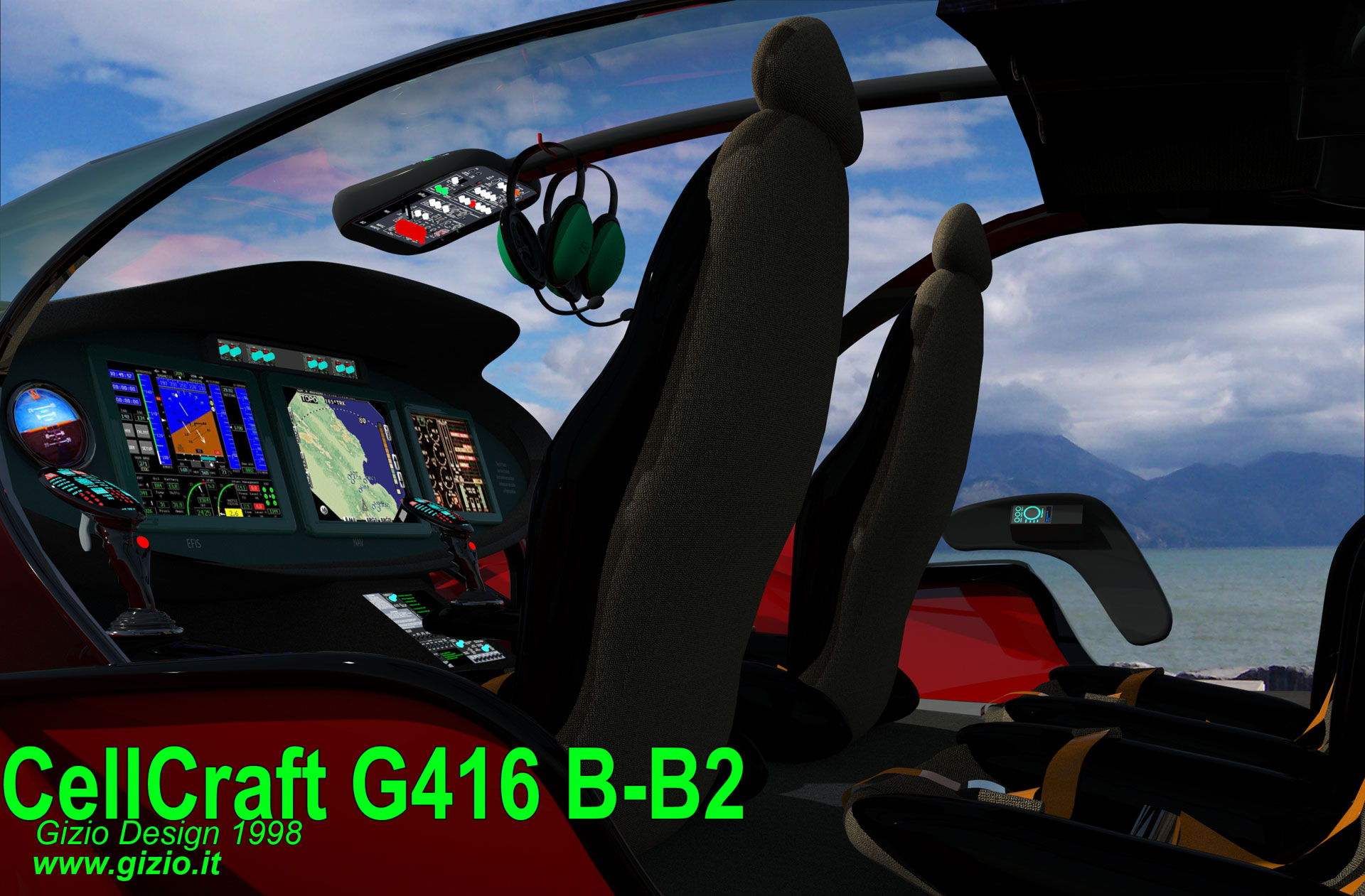
Pilot seat in the G416 cockpit was located on the left side and therefore the main display position was dedicated to the asset and main navigation functions as well for the control of the aircraft. It was then followed respectively by the screen dedicated to GPS and electronic navigation maps, placed in the meddle of the main panel, furthermore it could project images from external cameras which integrated a night vision system. The last display showed all the information related to the system and the engines as well the four compressors, including real time calculation of the available power, operating temperature etc.
The control of the aircraft in flight could be done thanks to two different type of joysticks, settled on both sides of the Smart Chair. Both, the yaw control and power would be managed through the action taken by the left joystick, while direction control is settled on the right side. The G416B/B2, the lates version, was equipped with pedals too, however in some particular situations the yaw control could work quite comfortable if activated automatically through the small lever placed below the power control joystick head.
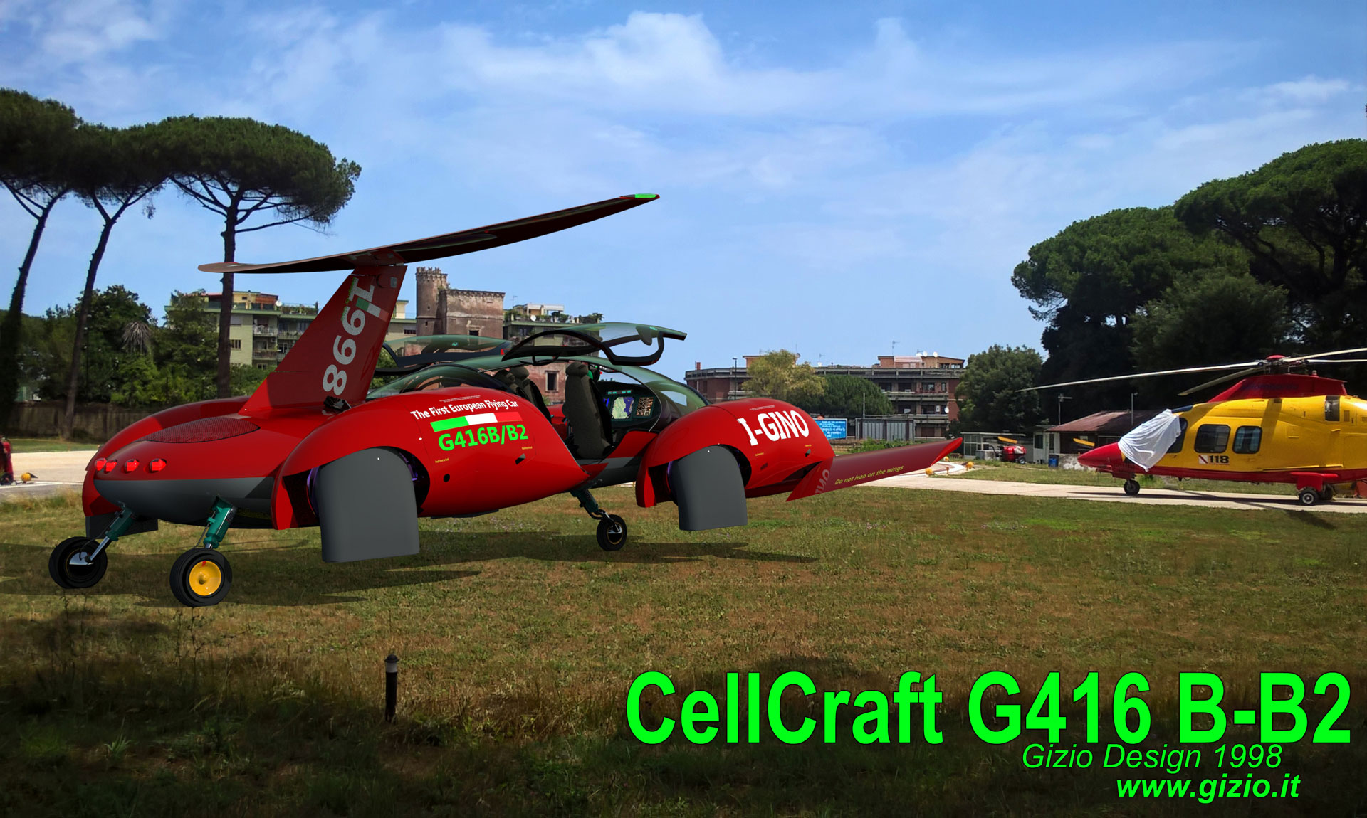
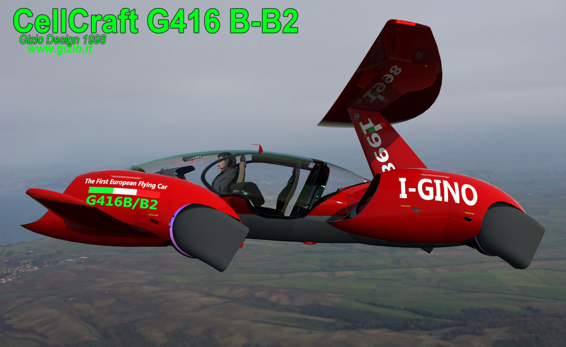
The main wing also was re-designed having a new shape, less sharp in order to increase lift but also improving the whole efficiency of the aircraft having a positive effect also on static stability, the main wing - or rear wing - makes the CellCraft a sort of biplane dynamic concept.
The rear wing was pretty smooth and has been shifted slightly forward than the original attack point since the center of gravity of the aircraft was mostly concentrated aft of the fuselage where both engines were accommodated.
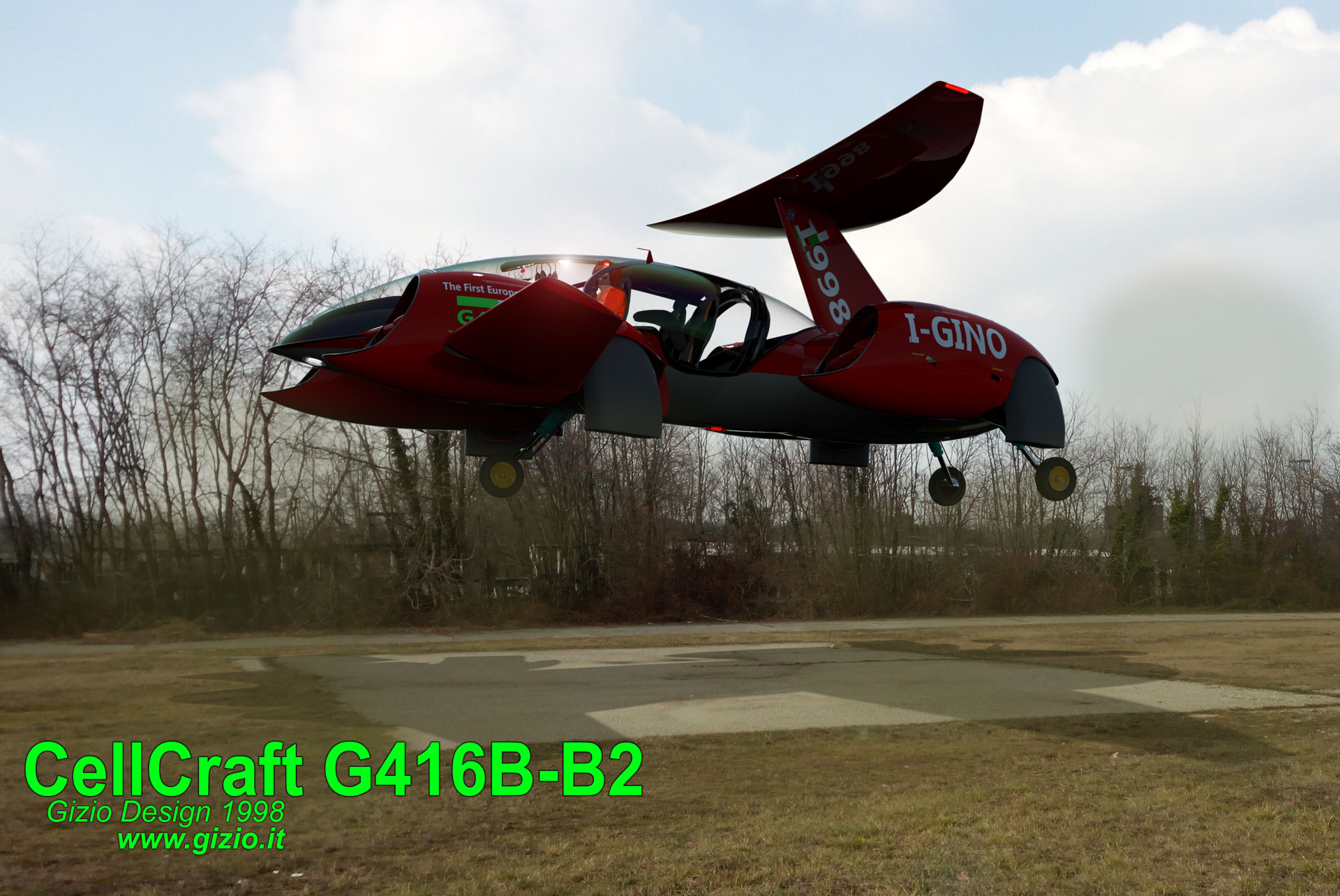
During vertical takeoff and hover flight, all the four splitters are oriented downwards ensuring the maximum thrust of the air “pumped” below the aircraft which as matter of effect will lift-up in the air the machine. In this phase the usable power was largely close to 110% for a limited time but with the aid of electric motors the pilot would get a good power/thrust ratio, to keep the aircraft flying in hovering for at least five minutes. Electric motors brought a further contribution, increasing the thrust. Once in flight the pilot would simply push the transition’s lever forward starting the computer sequence that would take in few seconds the aircraft moving forward from its steady point.
The control system of the G416B/B2 is represented by
the main computer (AFC), the control of this device
allows to tilting the four splitters backward, deflecting the thrust
in that direction that as matter of effect will reslut in a forward
acceleration of the machine. Once reached roughly 65 knots (knots)
lift produced from the wings and partially by the fuselage itself confer
a stable and smooth flight to the aircraft.
At this point the G416B/B2 continue to fly behaving
just like an airplane, capable of reaching a top speed of about 320
knots (592 km/h) without the aid of complex transmission system,
indeed the only four electric boosters connected solely with the generator
will make the four rotor spinning at the right angular speed with a
considerable saving of fuel, because the transmission and the related
mechanisc elementes systems result disconnected from both turbines which
now are solely working as turbo-generators.
The CellCraft was capable to take off and land vertically (H
mode) but also take off and land in airplane mode (A mode),
needed a few meters run, as well landing on a relatively short runway.
This further possibility could be particularly useful in situations
of heavy loading as well as to save fuel, wherever a runway would be
available but also in case of emergency lading, since the aircarft could
descent pretty well gliding behaving more or less like a sort of glider.
The G416B/B2 was the first project on which I began to apply the idea of building a virtual model in any single detail, from the basic structure to any little piece. It was thanks to 3D design software like Rhyno 3D in my case, that I really designed the aircraft as it was on the aper and before of that in my mind making it seems to be real. A 3D virtual model being gave me chance to evaluate its characteristics which before of that time the aircraft was just a mere fragment of my imagination, combined with my knowledge and experience as pilot and industrial designer.
This project was however the spark that lighted up a series of so many projects that came later, it's a very important steps also because I designed a new architecture for aircraft having a structural and a design absolutely compact and innovative. That allowed me to develop more and more advanced aircraft of this type and that could give more room to the technology of electric motors in the future in-fact one branch of my design production is to design some electric motor with a modular disk architecture, quite adaptable for many applications but unfortunately not described on side of this site for copyright reasons.
Many other projects followed the G416B/B2 later with most advanced technology as the G440 or the most advanced one the G450/55 which followed that initial idea based on the interaction between pilot and machine, but also in the development of new hybrid combinations and architectural structure of what CellCraft concept still represent.
©Gino D'Ignazio Gizio