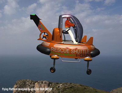
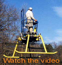
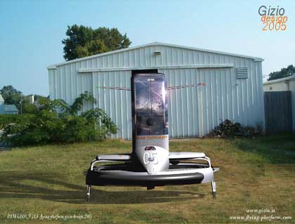
PAM Flying Platform (2005) Since the end of 40's experimental prototypes of a PAVs (PERSONAL AIR VEHICLE) were built and tested, some of they having a succesful flight. Among many there were a series of aircraft having the rotor settled under the feet of the pilot instead than above the head. This singular way to fly were subject to many controversy as well enthusiastic foreseen, the main target however at that time was to produce a large numbers of vehicle available for every single troop to allow them to move on the battlefield faster and be capable to over cross mines-fields. Most
of the time propulsion were produced by a twin counter-rotating
rotors, size of this type of aircraft varies with configuration,
there were ducted rotors like the HILLER VZ PLANE
(1955) or open rotors which has a major size in
diameter. In some cases like the De Lackner DH 4 known
also as Aerocycle, there was employed a sort of
bike-like configuration, others builders used jet tip blades system
avoiding to install the second rotor to counter act the typical
resulting torque generating in rotor systems. This was the case
of the Gluhareff MEG-3X (1960). ALPHA type was the first prototype designed for Pam Group, the project was just as starting point from were to conceive a more realistic and commercial project like the BETA and afterwards the DELTA and then the F-Vespa. |
 |
What is most interesting about those vehicles as well the PAM flying platform is the way they are controlled by the pilot. There is no need of special mechanical devices like cyclic mechanism as helicopter needs, tipical of upper rotor-craft configuration, but simply the pilot will simply and easy tilt his/her body in the desired direction doing so producing a momentum. As matter of effect the aircraft will be unbalanced and the trust produced by the rotor would do the rest moving the platform in that direction. Controlling aircraft like this remind the ride tecnique to control the asset of a motor-bike where the pilot shift the body and the bike will respond having the same asset. The platform is basically a sort of flying-bike after all. Pilot must keep a straight position, in the meddle of the platform keepeng the the centre of Gravity straigh down the machine. Power control can be obtained through the action of a joystick which change the collective angle of attack of all the blades, so the machine would rise up away from the ground. We may consider a project like this commercially positive and not to expensive to develop if we consider the technology we can have right in the palm of our hands. Micro electronics device and light plastic materials are quite available and this stuff should improve the efficiency of every single system, from the engine to the blade down to the controls, all aspect that would made pretty much the aircraft affordable. The Platform at the moment is still flying using a twin piston engine, however PAM GROUP is planning to experiment a twin turbine version that is the one I choose to develop my project for the firm, after all these type of motors are quite light, small and powerful compared to a conventional piston engine and that would make the platform more reilable. PAM GROUP declared that the platform wouldn’t fly higher that 30\ 40 meters by sea level, however like frequently happens technologies gives always one more chance at least to improve inventions like this, and the constant work and research for the perfection made by Bob Pegg, the chef engineer of the firm, will certainly improve the capacity of the platform in order to get the best performance, after all the turbines version didn’t fly yet, and we like to think about the Pam platform as well my F-Vespa to be as one of the main tools for safety and utility task all over the world of the next years. |
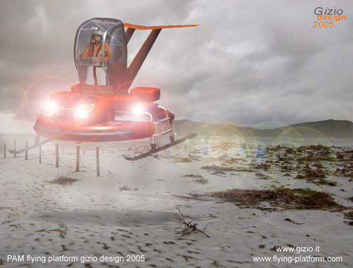
ALPHA It was the first prototype I deveoped for the PAM requiring an accurate study starting by every single aspect of the aircraft at least to give a shape to the future projects. In order to begin with the project, it's very important to make an accurate historical research. This type of aircraft is very interesting, the size, and the singular characteristics confirm that the idea could be potentially applied to many contests. So the result of my design is the fruit of many consideration that I’m trying to show to you along these articles, according to the original project made by the PAM GROUP. As you can see I covered the rotors first, it is the lift force applied to the aircraft, but are absolutely dangerous, especially in the position where they are. |
 |
A safe mission with such configuration would be quite difficult with these “rotating blades”, that’s why I designed this type of “bell-like” fuselage. It should be very light made by composite-plastic materials. Frame is made by aluminium and aeronautic steal, I kept an helicopter skid type beneath the body, adding two side steps, so pilot and eventually passengers in case of rescue operation could easily jump on the basement. There is also a landing gears version with 4 small wheels, capable to rotate all by 45° to maintain the stability on the ground like the legendary british WASP helicopter. All the four wheel similiar to those already employed on the CellCraft VTOL vehicle, can move autonomously the platform on the ground because of the four little electric motor installed in each of the wheels. So the pilot is protected with a transparent cabin transforming the flight control spot as a real cockpit; if required side doors can be add. |
As
you certainly noticed on both side of the cabin there are a couple
of handles, they are useful in case of rescue operation, as well
as to carry 2 more person, sideward but only for a short distance.
On both sides, respectively on the front and rear side, there
are 2 big pneumatic dumpers maintaining the aircraft safe in ground
operation in case of obstacles collision, as well as in case of
engine failure on water surfaces keeping the platform safely floating. The
last word is for the cockpit itself, there is a sort of seat next
to the Centre of Gravity, actually it is just a lean to keep the
pilot safely tied somewhere to the aircraft while flying. BETA I begin to study a more reasonable machine right after the ALPHA version, keeping my attention strictly to the PAM GROUP directives, which resulted as the BETA version. About engineering prospective the BETA presented in the beginning some problems, mainly due from the engines position that at the moment are settled on both side, and quite high over the pilot plane. That’s couse some little difficulties in the project, because such position create several limitation especially in the safety perspective because both engine are too close to the pilot feet, among all there is the access to the cockpit, that became a little uncomfortable for the pilot with these two engines placed on both sides. |
In order to protect the pilot from the external environment, a very light cabin 2.06 meter high, fixed to the main frame and covered by a plexi-glass transparent dome, can guarantee the safety and the comfort to the pilot, protecting he\she from dust, water and debrits, risen from the ground by the aircraft while flying in ground effect.
Finally a front and back cowling protect the tank, and the rest of the apparatus, necessary for a safe working of the aircraft, besides a stabilizer on the tail area should increase the stability impeding the aircraft having a nose down attitude out of limits in forward flight, that could result very light and essential though the aircarft fly at very low speed.
About
the controls , there is a small panel with turbine TOT
and RPM indicator one for each plus a double
rotor RMP tachometer, a TORQUE
digital indicator, a led TORQUE indicator,
and warning lights for the vital functions.
On the head of the power and directional Joystick there is the
ENGINE START switch; SHOUT DOWN engine
switch; and ENGINE TRIM switch,
all of these are doubled, one for each single turbine. A small lever
works as trim controls on the back side of the joystick’s head.
The direction of the aircraft insn't controled acting on the tail electric
rotor anymore like the ALFA model but directly
on both rotors through a system similiar as the largely installed on
most of the KAMOV helicopters, which works on the differential
lift between the upper and the lower rotor. On the left side of the
cokpit there is a simple handle necessary to help pilot to be clinging
to the aircraft while in flight.
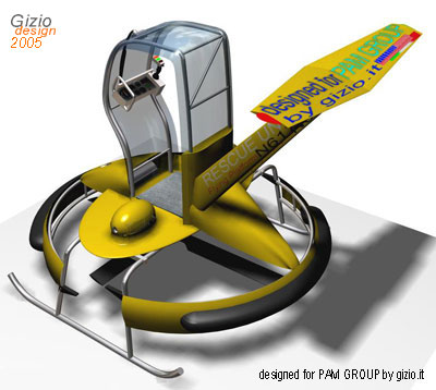
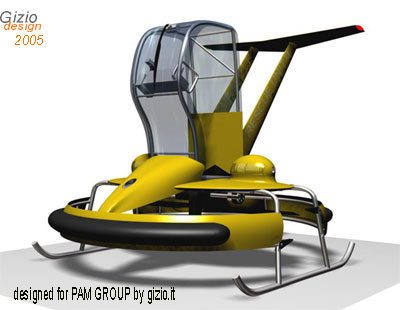
DELTA
In the Delta project the mission was easiest because here I had a full freedom on the project, altough costs were supposed to be as low as possible, therefore I made few basilar changing. One of the most important was of-course the position of both turbines. I did turn first both by 90 degrees and lowered them below the pilot plane, connecting the centrifugal clutch directly to the transmission shaft, with no need of any belt as happened in the BETA version.
The
Platform is intended as to be an utility vehicle, it can be used for private
as well for personal transportation but also pretty well for civilian
applications.
In both case or in any other situation the fulcrum of everything is the
pilot who fly on it, I'm thinking also about the commercial and industrial
perspective, how to produce it industrially? what kind of target we want
to strike? how many versions we can design? and, will the machine be furthermore
developable?
Safety is a must, as well as the ergonomic aspects of the machine. By my point of view pilot should find the aircraft easy to be manage and any single detail is important. The clear platform give pilot free access to the cockpit on both side as well as a clear escaping way, he\she would carry up two more people in case of rescue operation, or a couple of small box or anything else that can be fixed on both side of the cockpit, (fire fighting version will demonstrate this principle) .
Both engines has an easy access for maintenance, besides I deviate the hot gas produced turning the engine by 180° with a muffle that deviate the hot flow up, far from rotor or any susceptible element settled under the aircraft. Both engines are covered with a nice cowling on each side respectively on the front and on the back; the front one is provided of a has light for night operations useful in poor light conditions. Since I changed the turbines positions I've got some problems, ones of these was the distance between the transmission and the upper rotor, so I extended the landing skid moving the group transmission/rotor a bit below tha its original posizion keeping the system at a safe distance from any possible flapping of one or both blades of the upper rotor against any mechanical organ.
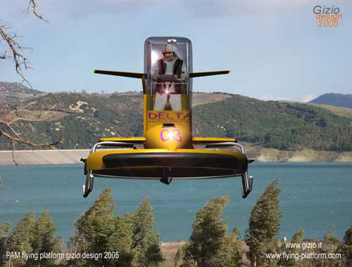
Everything is covered by an elegant wing-shape platform, that contain electronics devices, controls and vital systems, some more space can be obtained from the engine cowling that result quite large to contain more elements, included battery. Like the ALPHA and the BETA version ,the rotor is safely covered with a pneumatic front dumper, to protect the rotary area from collisions, it is a safe protection from anyone who unintentionally would find too close to the platform, it is also important in case of accident. In-fact the rotor must be confined in the ring reducing at the minimum the risk for the pilot, indeed DELTA has a protective grid-plane, very light but quite efficient.
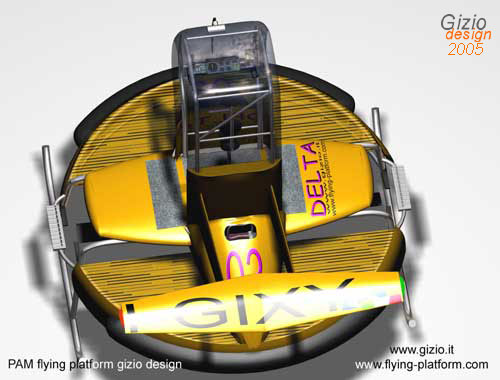
The main control for the platform is the done by shifting the vertical body position by tilting the bust to the desired direction, this would simply change the balancing of the plane accellerating it in that direction. The platform would follow the same direction because influenced by the producing momentum and the unbalancement of the body above the Centre of Gravity, so the pilot must stand-up in the cockpit holding a central position from where to move. I designed a sort of stool with some soft cushions positioned in specifics areas to keep the shoulder protected, and to hold the belt that pilot would be safely fasten before flight, the tripod can be moved according with the body position in every required direction, it is fixed to the main frame basement through a steal spiral, besides the stool can stand straight-up by itself.
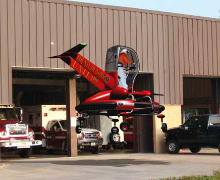
One of the most interesting application for the platform is the fire fighting version. This one I design is based on the DELTA platform and it is called DELTAF2, differently by the basic, it has landing gears useful to move the aircraft in and out from hangar or while on the ground.
This
platform is a bit higher and both water cannons can be controlled by a
small lever settled on the left side of the dash. I found several system
that could be succesfully employed in such aircraft for such purpose;
there is a large variety of water and foam cannons available also for
a flying platform like this.
This platform has four wheels electrically controlled with small servos
for autonomous ground movements. The aircraft in-fact could be on the
ground for refuelling or to be re-charged of foam or water, moving to
and away from the fire fighting tunk truck.
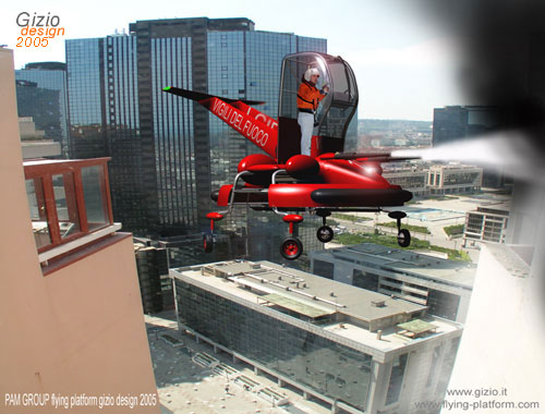
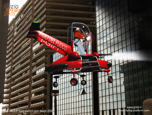
The compressor is powered by and additional power generator that supply the system required of the cannons. These two elements could be quite settled under the aircraft or even in the engine cowling vane. I made a couple of picture (above) just to demonstrate the utility and the potential employment of the DELTAF2 version as succesfully PAM’s flying platform.
No other machine can move so close to a building under fire attack as the platform might do. I like to image these aircraft in every single commercial port or within airport fields or involved in many other field, capable to fly over any surface to reach in few minutes the target.
Delta
Sk is a unique version of this kind,
it is basicaly designed for those climatic condition where temperature
is constantly below or close to 0° C, it
can be largely and successfully employed in such hostile environment where
a vehicle of this type could be vital.
In a special way my attention was pointed to the north European countries
like Finland where the nature of the territory
as well the climate maintains most of the inland inhabitant insulated
in the deep winter, indeed roads and tracks are mostly covered by a large
amount of snow that makes transportation slow and in some cases quite
impossible. This territory has wide and large valleys and huge lakes and
the platform can perform its duties quickly thanks to the low altitude
of these territory that seems to be quite adaptable for this aircraft.
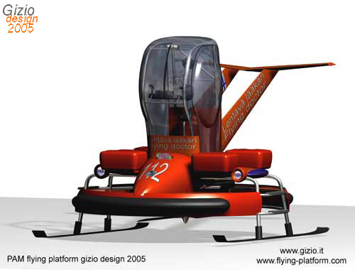
The vehicle act pretty much as a sort of flying bike and it could be addressed to medical emergency operation to be a perfect ” flying -doctor” tool. We can image a flying unit equipped with both medical devices and drug supplies, on an aircraft like this which could move everywhere within a wide area from village to village rapidly and efficiently, bringing the cares needed to whom are insulated by snow and cold.
Pilot
must be protected from the exernal low temperatures, from the snow and
icing rain, so I add 2 transparent side doors to the cabin and an internal
heating system.
Externally four rigid bags thermo-insulated
might contain medical instrumentations ,drugs,
and medical supplies, in other words all a doctor
needs to operate in any unforeseen situation, in brief he/she must be
able to give any possible assistance to remote sites in almost any condition
flying across ice lake.
Because of the low level of daily sun-light, some more lights must be
add to the external side of the cabin, and some position lights and beams
outside the fuselage, that will keep the aircraft clearly visible.
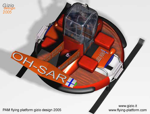
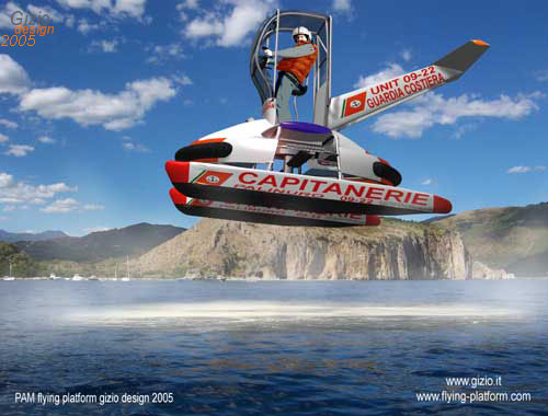
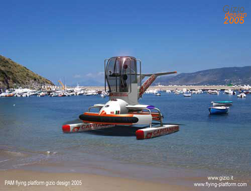
Delta SF is a marine version equipped with two light floaters adaptable as patrolling vehicle addressed to the COAST GUARD services or surveillance mission. The platform is very flexible, and capable to reach any craft not too far from the coast line for controls or for emergency operations like rescue and SAR.
The aircraft is basically built on the original DELTA version, and the landing skids are easy to replace simple removing a ring bolt that connect the frame with the two pneumatic floaters.
Both the floaters are made with black sea-prof treated marine-rubber, they are easy to swell and are also partially protected by a thin plastic skin with a metal steps on the upper flatted side, allowing pilot and crew to reach the cockpit without deteriorate the floater surface, all the floating structure is quite light and it would be less heavy than 20 kg.
Some
more important factor of the PAM ILV flying platform
must be analysed in order to complete my work on the project ,every
single detail was accurately studied keeping in consideration my experience
as commercial helicopter pilot as well as industrial designer .
As perfectly clear by the project and the intention of PAM engineers,
the way the platform fly is quite easy therefore it respond to a very
simple design.
The control of power needed to lift the aircraft up in the air is obtained through a lever which acting on the main counter rotating rotors simply varying the angle of attack collectively of all the blades. The control of the direction and the speed is obtained simply by tilting the pilot body in the desired direction producing a momentum which will have a considerable effect on the stability of the platform that will right after be inclined in the same direction pilot want to go.
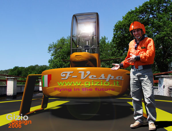
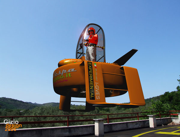
In 2006 I design the F-Vespa which basically come out by the same study made for the PAM flying platform. The aricraft is more close as I wish it should be, and since there was no cost limitation, since the project was basically virtual, I inserted in this aircraft some interesting innovation items like a GPS system, and an Augmentation Stabilization system.
The
main service panel include a double ROTOR TACHOMETER
for the rotor RPM parameters, then two TOT
indicator one for each turbine, and two RPM
indicator, one for each turbine. On the right side a bit
separated by those circular gauges there are respectively two
graphic TORQUE INDICATOR and a third panel which shows the
torque value numerically; this solution is very important it gives to
pilot at the same time both basic and fast information relate to the available
power in flight.
The right harm handle is fixed as well as the left one directly to the
console also fixed to the main frame of the platform , and a small lever
designed for the directional control , it is easy manoeuvrable by just
two fingers, the device is electronically controlled through precision
servos which will act straight to the tail rotor.
I can't predict the future, but probably this type of aicraft would have a further development ahead, or may be not, what is very important is that these projects gave me the opportunity to discover another possible idea related to rotor systems, so some more project were made along this study after the F-Vespa depelopment with two more model and a remote controlled aicraft.