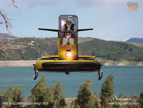
DELTA In the Delta project the mission was easiest because here I had a full freedom on the project ,therefore I made few basilar changing. One of the most important was of-course the position of both turbines; I first turned both by 90 degrees and lowered them below the pilot plane ,connecting the centrifugal clutch directly to the transmission shaft, with no need of any belt as happens in the BETA version. |
I
want to make clear my position to the reader, my modification do
not indicates that I’m right above original engineers design,
but only as a simple alternate version of the project in the way
I like to see it as designer and of course as pilot too.
The Platform is an utility vehicle, it can be used for private as
well as for personal transportation but also pretty well for civilian
proposes. Safety is a must, as well as the ergonomic interface with the machine. By my point of view pilot should find the aircraft easy to be manage and any single detail is important. The clear platform give pilot free access to the cockpit on both side as well as a clear escaping way , he\she would carry up two more people in case of rescue operation, or a couple of small box or anything else that can be fixed on both side of the cockpit,(fire fighting version will demonstrate this principle) . Both engines has a straight access for maintenance, besides I deviate the hot gas produced turning the engine by 180° with a muffle that deviate the hot flow up ,far from rotor or any susceptible element under the aircraft. Both engines are covered with a nice cowling on each side ,one on the front and the other on the back;the front one has landing light for night operations also useful in poor light conditions. In order to modify the engines positions I had many problems still to be solved , ones of the worse was the closeness of transmission with the upper rotor , so I decided to tight a bit the landing skid and lengthen the rotor must the engines will be at a safe distance from any possible flapping of one or both blades of the upper rotor against any mechanical organ. |
 |
|||||
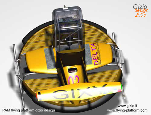
In
consequence of these I did modify both fuel tanks, positioning right
where they are in the opposite direction, respectively one on each
side, refilling the tank is possible simply open the small square
side step, both tanks seems completely hidden and protected from
the external sight . Everything is covered by an elegant wing-shape platform, that contain electronics devices, controls and vital systems, some more space can be obtained from the engine cowling that result quite large to contain more elements, included battery. Like the ALPHA and the BETA version ,the rotor is safely covered with a pneumatic belt, in front and back just to protect the rotary area from collisions , it is a safe protection from anyone who unintentionally would find too close to the platform , it is also important in case of accident , in-fact the rotor must be confined in the ring reducing at the minimum the risk for the pilot, the DELTA has a protective grid-plane , very light but quite efficient. |
 |
 |
|
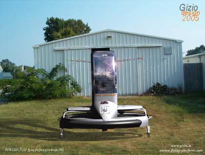
The
innovation in the project is the standing tripod . The main control
for the platform is the body position , moving the upper side of
it ,tilting it in a due direction, would change the balancing of
the plane. As matter of effect the platform would follow the same
direction because influenced by the producing momentum and the unbalancement
of the body on the platform plane , so pilot must stand-up in the
cockpit holding a central position from where to move. In order
to tie safely the pilot to the aircraft I designed a sort of stool
with some soft cushions positioned in specifics areas to keep the
shoulder protected ,and to hold the belt that pilot would be safely
fasten before flight, the tripod can be moved according with the
body position in every required direction, it is fixed to the main
frame basement through a steal spiral ,besides the stool can stand
straight-up by itself . |
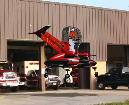
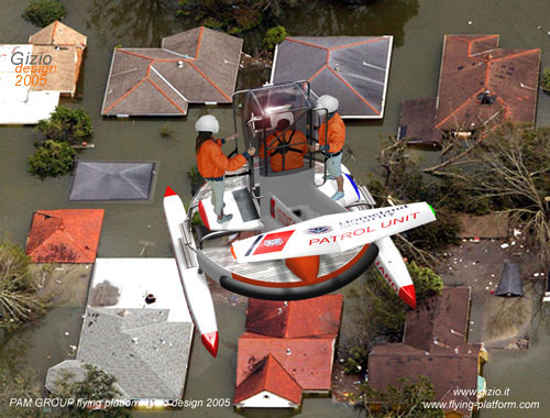
One of the most interesting application for the platform is the fire fighting version. This one I design is based on the DELTA ones and it is called DELTAF2, differently by the basic, it has landing gears useful to move the aircraft in and out from hangar or on the ground.
This
platform is a bit higher and both water cannons can be controlled by a
small lever settled on the left side of the dash .I found several system
that could be succesfully employed in such aircraft , there is a large
variety of water and foam cannons available also for a flying platform
like this.
This platform has four wheels electrically controlled with small servos
for ground movements. The aircraft in-fact could be on the ground for
refuelling or to be re-charged of foam or water ,coming close to the fire
fighting track.
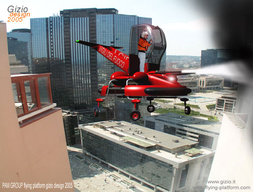
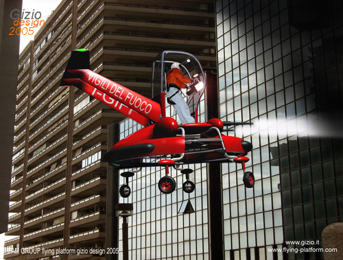
On the front side, quite clear visible, there are two foam-cannons or
water spreader , four tanks on both side, the front one are a little bit
smaller in order to compensate the weight of the front cannons.
The compressor is supplied by and additional power generator that supply
the sistem for the cannons. These two element could be quite settled under
the aircraft or even in the engine cowling vane.I made a couple of picture
just to demonstrate the utility and the potential employment of the DELTAF2
version as succesfully PAM’s
flying platform extraordinary idea.
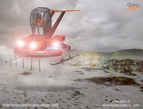
In a special way my recent attention was shift to the north European countries like Finland for example where the nature of the territory as well the climate ,maintain most of the inland inhabitant insulated in the deep winter, cutting those community for long periods out for the rest of the word, indeed roads and tracks are mostly covered by a large amount of snow that makes transportation slow and in some cases quite impossible, besides, the territory has wide and large valleys and huge lakes , the platform can perform its duties quickly thanks to the low altitude of these territory that seems to be quite adaptable for the platform.
Obviously
my research is mainly addressed to those tasks relate to rescue and
medical assistance, however we can image a version for the Alaskan piper
line surveilance ,where a wide territory must be overseen for pipes
maintenance.
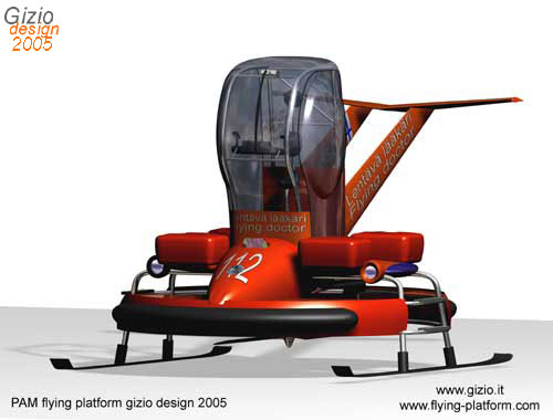
The vehicle act as a pure flying bike and can be addressed to medical
emergency operation as I mentioned in some preceding articles, where
I talk about the property among many of this type of aircraft, as very
useful as to be a perfect ”
flying -doctor”. We can image a flying unit
equipped with both medical devices as well as emergency drugs , be able
to make the aircraft flying safe ,moving it everywhere within a wide
area from village to village rapidly and efficiently , giving the care
needed from those whom are insulated by snow and cold.
To make the aircraft adaptable for this task some modification occurred
by the original DELTA
version , the most evident is the landing skid which became flattered
having a ski shape-like allows the vehicle to land safe and maintain
itself on the ground steadily.
Pilot
must be protected from the exernal low temperatures, from the snow and
icing rain, therefore I add 2 transparent side doors to the cabin and
an internal heating system.
Externally four rigid bags thermo-insulated
might contain the medical instrumentation
,drugs , medicines,
and all that doctor need to operate in any unforeseen situation , in
brief he/she must be able to give any possible assistance to remote
sites in any condition.
Because of the low level of daily sun-light , some more lights must
be add to the external side of the cabin , as well as more position
lights along the fuselage, that will keep the aircraft clearly visible.
About the instrumentation , there is no doubt that even though the aircraft is designed for VFR flight conduction , adding some essential navigation instruments is absolutely necessary, think about an ADF useful to find radio emission coming by private radio station, also a digital GPS in some cases vital, and a radio locator.
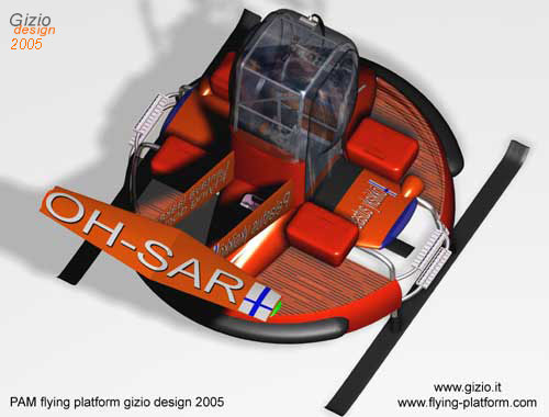
Delta Sf is a marine version equipped with two light floaters adaptable for several employments as vehicle to those important task addressed to the COAST GUARD services or surveillance mission. The platform is very flexible , and capable to reach any craft not too far from the coast line for legal controls or for emergency operations like rescue and SAR.
The aircraft is basically built on the original DELTA version , and the landing skids are easy to replace simple removing a ring bolt that connect the frame with the two floaters.
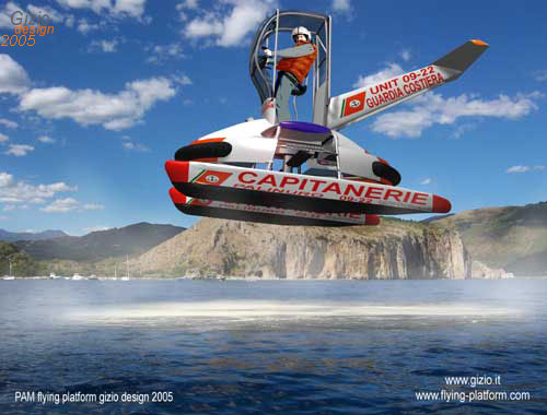
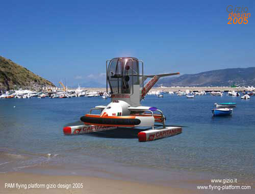
There are several versions of this platform, some are also available with full transparent side doors and external steps, this last version is capable to carry up 3 person included of pilot for emergency operations on the territory , we suggest the “flying doctors” a flying crew capable to reach the area with a low rate of access and thanks to the platform they will be capable to land on the site and applying the first aid to patients who needs of immediate help.
As perfectly clear by the project and the intention of PAM engineers ,the way the platform fly is quite easy therefore it respond to a very simple design for this type of aircraft , those aspect are as well important if we consider the interaction between machine and pilot , indeed they became more important if the designer keep in mind every possible critical situation as well as any imaginable mission the aircraft might be involved.
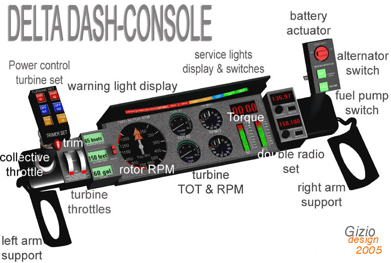
What appear very important in this project is the perfect disposition of every single command, warning light, switches and anything else must be kept under control and obviously within pilot sight control area.
It’s in-fact very comfortable for the scanning process and the hands movement the reduction of the action on commands mantaining almost everything reachable fast in short time and with intuition, after less than a hour of familiarization indeed it will result absolutely instinctive.
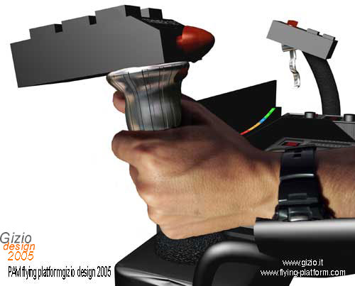
The
head of the left arm handle contains respectively the MAIN
COLLECTIVE CONTROL TROTTLE in the upper side, right
above the collective control there is the TURBINE
SET BOX wich contain the TRIM
LEVER and the following keys: TRIM
SET KEYS N1 and N2 , they are lighten in yellow
, pushing one or the other switch the trim will be activated so once
it is on it will influence any action on the selected engine to tune
the RPM's correctly , after the trimming is
completed the key must be turned off ; the system memorize the last
tuning maintaining the chosen parameters.
ENGINE SHUT DOWN KEYS N1 N2
are both fuel cut off switches, ENGINE
START KEYS N1 N2 are both for the starting of either
turbines.
In
order to save space inside the cockpit due also to the reason that everything
must be contained within a small area , I designed two little cylindrical
turbine throttles settled on the lower panel, left sideward of the left
handle .Throttles are twins , a safe lock red key allows pilot to keep
the position once he/she rotate to the next setting , there are three
basic option : OFF
; WARM ; FLIGHT.
Both throttle are electronically controlled by servos which act directly
on the main gas controller settled on both turbines: simply and easy!
The gauges are all digital. The platform isn’t a fast aircraft and all operation must be conducted within VFR flight rules at relative altitude and speed, therefore the ALTIMETER was designed with the same basic consideration, and it can be settled with the local altitude before flight.
The
fuel indicator which measure the amount of kerosene expressed in gallons
is placed as final instrument indicator, this display will blink when
a fuel reserve is reached producing a rhythmic chain sound as main alarm.
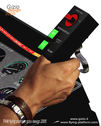
Warning light are all settled on the left side, and those are mostly
related to engine function they are also disposed as follows: LOW
RPM ; OIL
PRESS N1 ; OIL PRESS N2;
OVER TORQUE ; TOT WARNING N1
; TOT WARNING 02 ; TRANS OIL TEMP;
BATTERY LOW TENSION.
Pilot must become soon familiar with all the main functions and alarms is settled on the left area , and that is easy to recall because the power controls are placed too in that position, therefore in case of malfunction even if the attention at moment is outside the aircraft , there is no doubt that any light blinking on the left side will represent a problem, therefore the message will arrive to the pilot mind immediately and it will be clearly recognizable .On the other side of warning panel light there is the area dedicated to the service lights , those lights are different in colour and at moment they are placed as follow: LANDING LIGHT: ANTICOLLISION LIGHT; POSITION LIGHT.
Service
light indicators works as switches too, pilot will simple push the blue
or the green square indicator to actuate the desired service, this double
function is exclusively and only for service functions this saved space
weight reducing the complexity of the entire console.
The main service panel include a double ROTOR
TACHOMETER for the
rotor RPM parameters, then two TOT
indicator one for each turbine, and two RPM
indicator, one for each turbine. On the right side
a bit separated by those circular gauges there are respectively
two graphic TORQUE INDICATOR and a
third panel which shows the torque value numerically; this solution
is very important it gives to pilot at the same time both basic and
fast information relate to the available power in flight operation through
two wide vertical line , and a second which shows the exact value of
it at any instant.
The right harm handle is fixed as well as the left one directly to the
console also fixed to the main frame of the platform , and a small lever
designed for the directional control , it is easy manoeuvrable by just
two fingers , the device is electronically controlled through precision
servos which will act straight to the tail rotor.