Interface between man and machine

The project CellCraft -as I’d already wrote in other pages of this site - began initially as an idea which included the review of some architectural elements related to the cockpit as well introducing new type of flight controls. This included an accurate study for the development of an integrated system which would be a perfect interface between the pilot and the aircraft, a system like that tough pretty much complex would be efficient as well interactive and can guarantee a high level of safety particularly in emergency situation.
In the beginning I was pretty much concentrated in conceiving a new idea for a helicopter cockpit that would solve some remarkable problems belonged to this type of aircraft, redefining a more active and interesting architecture of it. Since the early nineties I began to glimpse an interesting development for both hardware and software available at that time for home application or very low complex devices. I thought that such applications could be pretty much adaptable to a flying systems, so I decided to start from that point ahead trying to draw an imaginary model of an ideal cockpit for helicopter.
The first step was to start with the human element: the pilot. The best point of observation for me was of-course starting to look at the whole situation particularly from the pilot seat view, then thinking about the flight controls system since it is the first elements of “communication” with the aircraft. Later my attention was focused on both quality and quantity of information required for the conduction of the flight, establishing a degree of importance, the right sequence of information and finally a system that would be capable to manage the whole situation.

These were the basic elements which initially I considered vital in order to design a new environment, getting a system that would be ideal for an efficient interaction between pilot and aircraft. In the past years I worked as a helicopter pilot flying on various rotorcraft nut spending most of my flight time on Bell Jet-Ranger, as well getting a couple of hundreds hours on airplane. I was already graduated as a industrial designer at that time so my attention become even more attracted by the aviation environment focusing most of my attention to that extraordinary flight environment.
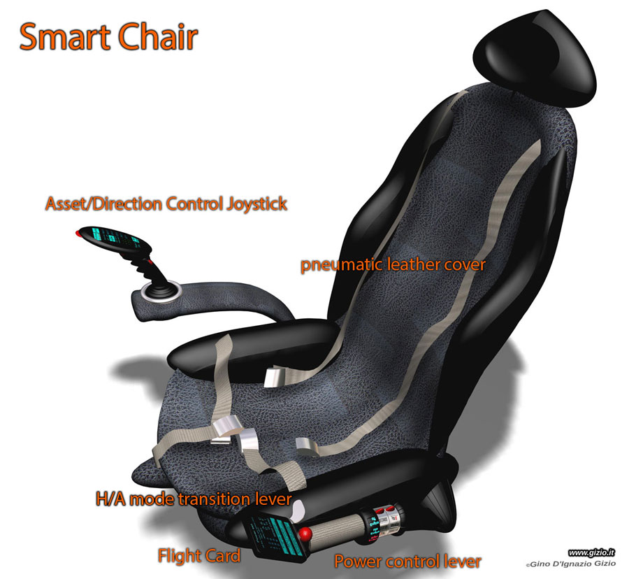
The daily contact with helicopters allowed me to develop an intense study of this type of rotorcraft, having the opportunity to design my first project, a special helicopter provided of ducted-rotors: the
DDRH (Double Duckted Rotor Helicopter). The machine had a cockpit very similar to what I drew later for the CellCraft G150.
Thanks to the development of this type of project, that stimulated me so much, becoming a very enthusiast of this type of design that took me slowly and constantly to complete it finally in every single detail. The cockpit in the beginning wasn’t quite resemble a helicopter one, but it matched exactly with all that was in my brain at that time.
What I was dreaming since then was a sort of machine able to fly both in vertical mode as a conventional helicopter as well horizontally like an airplane. Be radically innovative having a hybrid propulsion system, which would eliminate or reduce the presence of some heavy and very inconvenient mechanical component, nor heavy and complex transmission gear-boxes or any type of hydraulic multipliers.


Smart Chair

The SMARTH CHAIR represent the beginning of the entire history of my projects and the consequence of the subsequent development of the CellCraft. This “device” is a little resemblance to what we consider the classic pilot seat, however its architecture is indeed belonged to its multitude functions that in this case change significantly
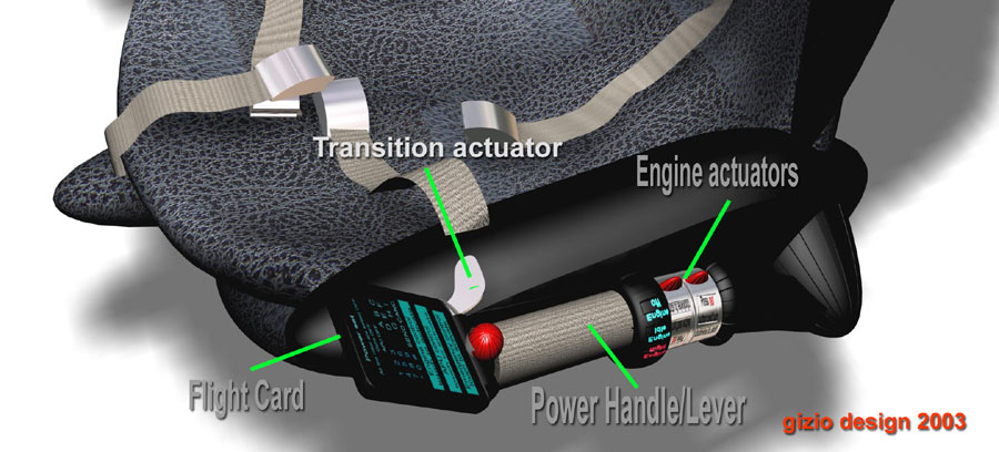
 its original meaning.
The seat is built on a frame of aluminum and only few components are made of lightweight steel. The whole seat is covered with a series of pockets pneumatic chambers, which make it particularly lightweight and comfortable as well anatomically pleasant, reducing the stress sustained from long time flight. A special sensor in-fact can calculate the pressure variations of the body of the pilot exerting on its surface defining the level of accelerations occurring, by interacting with the AFC which as we will see further ahead will play an important role also related to SmartChair.
Pilot can program a series of parameters, such the position, stiffness or the level of interaction with the aircraft, recalling and set pre-memo preferred setting and many other parameters at any time, through the board controls. Most of the “personal” pre-storing set-up are mainly memorized in the on-board system as well updated in a small device called
FLIGHT CARD.

Inside the SMARTH CHAIR there are accommodated some electronic important elements, as well the sensors of the pneumatic pressure as described above. There are three accelerometers, respectively for the measurement of accelerations occurring on the three axis, these parameter can be measured through the variation of the pilot body weight (angular acceleration of the body).
All these information as well those coming from the flight controls are sent to an electronic system of interpretation and data processing. Then all that will finally be converted in digital packs moving via a twin optical cable straight to the AFC Automatic Flight Control).
The
SMARTH CHAIR is therefore a true single independent component “a cell” a very fine control interface, in other words the “translator” between Man and Machine.

The SMARTH CHAIR can be installed or removed aboard the aircraft through a simple and easy operation which takes just a bunch of minutes and one person to replace it.
The housing structure on the floor of the aircraft is made of an alluminium bolted platform, at the center of which there is a fiber optic connector and a second cable for few supply voltages plugs; that’s all!
The optical connector allow transmission of both input and output data, like the positions of the commands, interventions on them, the activations or deactivations of functions, or all those information processed in a graphic form, being published on the display or on the directional control head, recorded in real time in the 64 Gb FLIGHT CARD memory.
The
SMART CHAIR can also be mounted on a special platform and connected to a digital system that will reproduces a virtual aircraft once it is connected to a computer having installed a dedicated software. This allows the diagnostic software to reproduce any single moment of the flight re-playing it on a ground computer station, a very useful procedure for the re-programming and verification of the state of the aircraft element, as well as simulation platform for training.

Once the aircraft is on the ground for technical checks it is possible to diagnose the state of the machine through routine maintenance connecting the diagnose computer to the AFC for the electronic control and the related diagnoses. Some of the technical check can be also made even while the aircraft is in flight through a satellite remote system, from any location through transmission data via GPS satellite system to a central server on the ground.
At the end of each mission by updating the data processed through the
FLIGHT CARD, you can re-call all flight parameters analyzing them on a standard computer through instantly and efficiently with a very accurate analysis. This system allow you to look back at both the conduct of the flight and all flight parameters related to the mission already followed.

The architecture of the aircraft resemble ad idea in wich different group of elements according to a specific pattern, are interconnected with single cells, easily splitting in short time for maintenance proposes, thanks to a modular system and the high technologies available today - and perhaps tomorrow - flexible and perfectly integrated in a compact flying system called CellCraft. The next future will see new concepts that maybe could match or even represents projects like those on this site.

The SMARTH CHAIR is one of the vital cell of the machine, a singular element. It combines a number of functions and commands just placed around the pilot, pretty unusual if compare it to a conventional aircraft where instead most of switches, knobs and lights are pretty much spreader separately in space and positions all around the cockpit.
The chair is able to interact independently communicating with the machine in both directions, facilitating the task of the pilot, improving the quality of flight and any apparent umpredictable operation.
A system like this in-fact could extend quite forward a good part of the possibilities offered by this technology, which allows to piloting the CellCraft easily, even by whom does not have the use of legs, as well to anyone who wants to try for the first time to fly on this wonderful machine, thanks to a tutor-dynamic system which works as a self protective device, guarantee safety and performance to the aircraft; the passengers; the pilot.


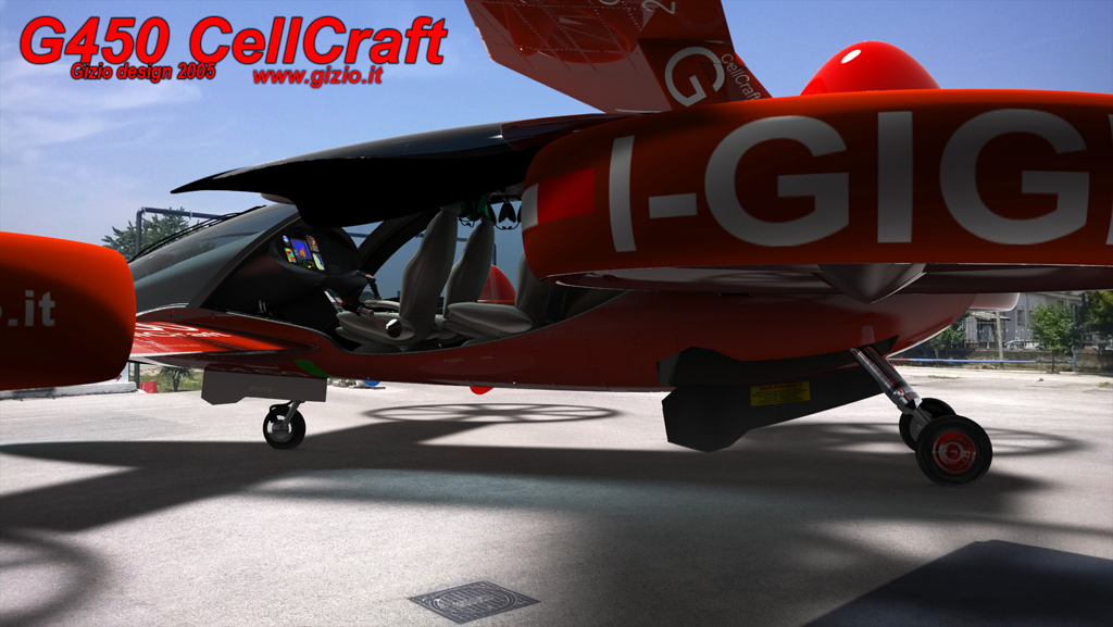
Tactile dispay and console

The idea behind the project was initially to review the cockpit itself, particularly the arrangement of actuators, switches and all those mechanical elements distributed around the pilot's seat, often incorrectly, confused and un-ergonomic. I wished to fund a new way to integrate all these devices into a compact system visible and easily accessible, separating them by type and function. This was one of the main goals that I wanted to achieve since the first project: the DDRH.
In the first half of the nineties there were already tactile displays, mostly used in machines for engineering purposes, they were simply the interface between the operator and the numerical control machines. These devices were very simple after all, indeed the main screen has a very thin plastic layer that worked as a sort of switch grid. The operator actually didn’t really touched the display but he pressed his finger on the screen stimulating the thin electric grid placed on the screen. A back ground graphic icons projected on the screen created the illusion that the screen would be tactile and the operator would “impressively” acting on it. Touch screen today are pretty much different of-course!
However that simple device stimulated my imagination since then, with the idea of using such technology to develop later a number of devices such as mobile phones, computers and other type of equipments, since 1998
(see Electronic section).
One of the most interesting applications which I started with since the beginning, was the idea to design a kind of perfect cockpit, a system where all the main switches and functions of activation-deactivation devices, were grouped on a single screen through graphical symbols (today called icons) and menus. All that easily projected on a tactile screen; in other words a display that would work as a central command unit.

The first attempt to design such a system was introduced before the CellCraft even appeared, and it was introduced on the DDRH (1995-96), a particular type of helicopter provided of ductedn electric propellers. It has just one single display that would projected everything pilot would need from navigational instrumentation, up to the of motors monitoring, in other words the screen would be able to reproducing a sort of virtual panel control, which contained lights and emergency alert, as well activation switches for the various vital functions. The DDRH was equipped with a joystick which acted electronically on the aircraft since it hasn't any cyclic control system, since the airfraft flew through two parallel electric ducted rotors. The concept for this type of helicopter resembled already in some aspects the future idea that came later in the form of the CellCraft. This strange helicopter in-fact represented an experimental basis for starting the new projects to come.

The power control of the DDRH consist of a small lever placed on the left side of the seat. Both control levers including pedals were both activated through a fly-by-wire system that operated thanks to electric servo-actuators, through a simple electronic system that multiplied proportional displacement of the levers, within a millimeter scale movement of the axes of rotation of the rotors. All those devices are present today on all CellCraft models, DCL (Directional Control Lever) even tough pretty much technologically evolved.

In the G150’s project, all the information coming from the management system was concentrated in a single display, that worked also as main operative control device, it displayed as well all the main functions of the machine but the complexity of the project was a bit higher than of the DDRH, however both the projects opened the way to the CellCraft. In addition with this system there was also the introduction of vocal commands, that although limited in their operations, constituted a further interesting possibility, which was later developed further in subsequent projects, according with the evolution of both computer and software at that time that was very fast and impressive.

This section is mainly dedicated to both projects, the CellCraft G450 and G455 equipped with a tactile display device made of three different units, one for the navigation and the other two for the flight parameters management and actuation devices; like virtual switches etc and GPS map navigation.

Through both displays pilot can recall several functions, moving icons or even re-programming more complex ones in a certain position of the screen as you like, changing the size of it etc; in few words you can finally be able to customize the whole layout. All that digital stuff will be stored in the Flight Card memory and can be recalled to the next flight loading your preferred parameters.
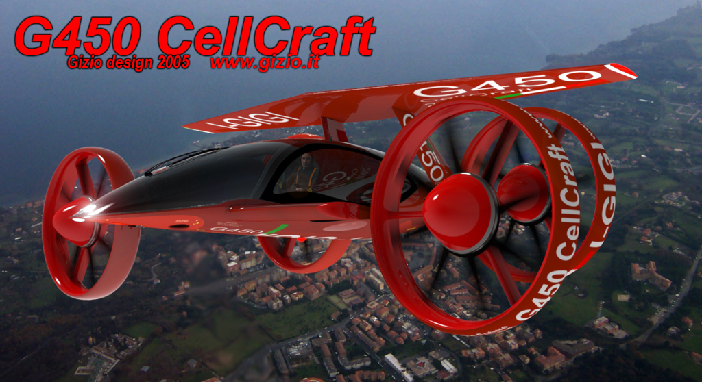
The machine is equipped with a third touch screen, located on the center front top of the cabin, which displays all the information coming from the AFC, including those related to the rotors, engine-generators and systems connected to it.

 
Rotors

The CellCraft is provided with eight three-phase induction motors with permanent magnets electronically synchronized through a digital device RRC (Rotor Control Revolution) which sends a continuous sequence of electrical pulses coordinated with the position of the magnets of the rotor. The pulse frequency is calculated by the control system with extreme precision and it can guarantee a perfect synchronism. Each motor can produce an average power of 50 kw for a total available power of 400 kw. The motors are assembled inside the rotor chamber in pairs of two and are connected through an internal mechanical system.
Rotor blades are made of carbon fiber and lightweight steel core, they are suspended on a special rubber-dumper support, which ensured a limited excursion, avoiding mechanical tearing due to continuous variations of Rpm speed and angle of attack. Each individual blade is mounted on a special ring, a bearing which allows it to rotate on its horizontal axis of a maximum value of 5°. Then a second fixed ring connected to the axis of rotation of the blades works collectively in order to change the variation of blades pitch through a twin electromechanical servomechanism, arranged inside of the head of each rotor only while in hovering flight.
The ring surrounding the rotor protects the blades from external impact as well working as a support for the aerodynamic ducted structure, since is well known that this device reduces dramatically the induced drag generated on the blade tips
(see Helicopter Aerodynamics).
The rotor is made of a pair of aluminum ring frames supporting the outer shell made of plastic material. Both, the motors and rotors are fixed on a steel ring suspended on three arms, one of which passes through the wing to which the rotor is connected, allowing it to tilt for a maximum total angle of 120°; respectively 90° forward and 20° degrees backward respect of the horizontal plane.

The rotor mast that supports each rotor is placed across the longitudinal axis of the relate side wing, it is a tubular structure through which both the power cables of the two motors forming the rotor, as well the optical cable designed to convey the necessary digital information coming from the various sensors sends signals constantly to the AFC located in the meddle of the fuselage body.
A pair of powerful electric servo mechanisms works assuring the rotation of each single shaft connected to the relate rotor ring, allowing pilot to move it forward, backward or yawing the aircraft in flight. The four rotor mast will accomplish a progressive rotation forward to a full angle of 90° degrees from the original horizontal plan. The rotation will take place in a synchronized manner simultaneously in order to have all four rotors on the same plane of rotation at the same time.

Smarth Chair allows all the operation as described above easy and safe for the comfort of the pilot and the passengers.

©Gino D'Ignazio Gizio